
At a glance
- Problem
- Recharging the implant meant assembling a corded paddle, a separate charger, and a belt or patches, then hunting for alignment under burn warnings.
- My role
- Industrial design of the next-generation charging system: paddle, power pack, belt, and feedback.
- Result
- Final paddle design went to Engineering as two options with sub-options; the charger transfer wasn't resourced before Nuvectra wound down.
- Client
- Nuvectra
- Role
- Industrial designer for the next-generation charging system (title: Usability Engineer)
- Timeframe
- Late 2017 – early 2019
- Team
- Industrial designer, working with Nuvectra's mechanical, electrical, and systems engineers
- Disciplines
- Biotech · Injection Molding · Usability Engineering · Regulatory Documentation
- Client
- Nuvectra
- Role
- Industrial designer for the next-generation charging system (title: Usability Engineer)
- Timeframe
- Late 2017 – early 2019
More details
- Team
- Industrial designer, working with Nuvectra's mechanical, electrical, and systems engineers
- Disciplines
- Biotech · Injection Molding · Usability Engineering · Regulatory Documentation
Context
Nuvectra’s implanted neurostimulators run on a rechargeable battery. Patients top it up through the skin: a charging paddle placed over the implant transfers power inductively.
From late 2017 to early 2019 I was the industrial designer for the next-generation charging system. The brief came with three goals: lower manufacturing cost, easier use, and better robustness.
Problem
The legacy charger wasn’t one bad part. It was a system patients had to assemble and get right every time they charged: a corded paddle, a separate programmer-charger, a belt or adhesive patches, and a search for the sweet spot over the implant.
- Assemble the kit Connect a corded paddle to a separate programmer-charger.
- Strap it on Hold the paddle in place with a belt or adhesive patches.
- Hunt for alignment Move the paddle until the alignment icon appears.
- Watch the heat Charge under warnings about paddle heat and skin burns.
- Repeat Do it all again at every charge.
The manuals themselves documented the pain points:
- Patients were told to move the paddle until an alignment icon appeared.
- Deeper implants made alignment harder.
- The paddle carried warnings about heat and burns during charging.
- Setup depended on a belt or adhesive patches to keep the paddle in place.
Constraints
Physics set the rules: inductive coupling falls off with depth, and the manuals flagged implants deeper than 1.5 cm as harder to align.
- It was a regulated medical device, so every change had to live in the design history file.
- The coil and charging electronics already existed; the design had to work around them.
- Mechanical engineering was a shared resource across several programs.
- System-level parameters were still moving while the industrial design progressed.
What I did
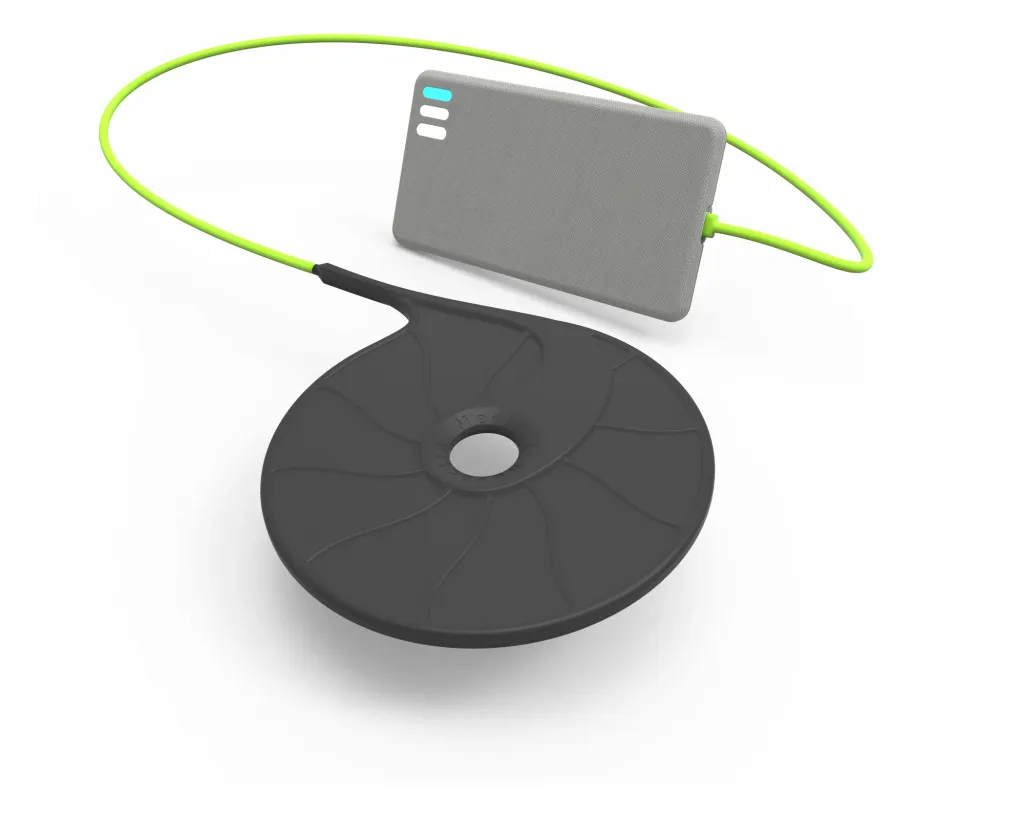
The key move: design the system, not the part. Instead of restyling the paddle, I started by defining what the paddle, the charger, and the cable between them each had to do for the patient.

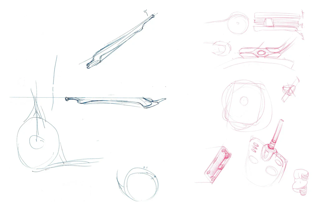
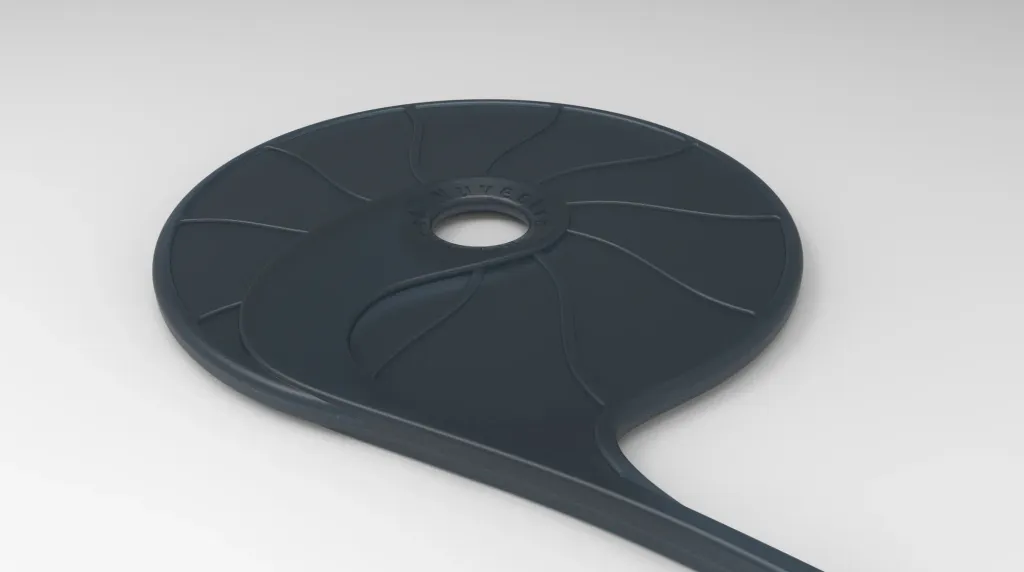
The paddle: two directions for the same coil. I took the paddle through to final industrial design in two options, each with its own sub-options.
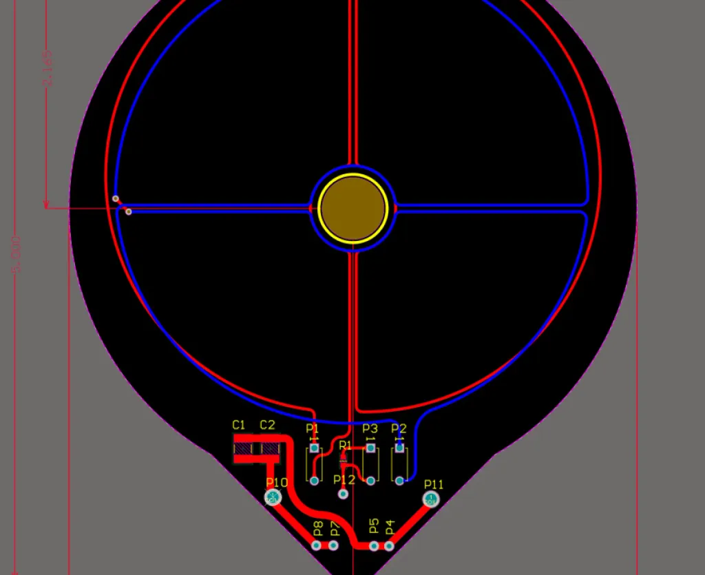
Flexible: a paddle that conforms to the body, with sub-options for how the coil connects to the cable, from a flex circuit to a dedicated return wire, plus an overmolded strain relief and a high-reliability cable.
- Rigid: a thin, stiff paddle as the alternative direction.
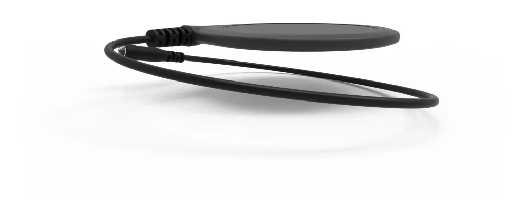

The charger: one wearable unit, not a kit. Around the paddle I designed the rest of the system so charging could become one simple routine:
- A power pack with built-in indicators and a rechargeable battery, with a paddle connection the patient never has to detach, so there was nothing to assemble.
- A belt specification for wearing the pack and holding the paddle in place.
- Charging feedback through sound and touch, so patients didn’t have to watch a screen to know charging was working.

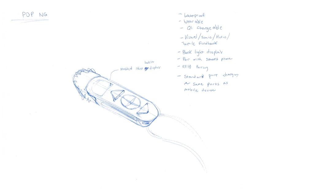
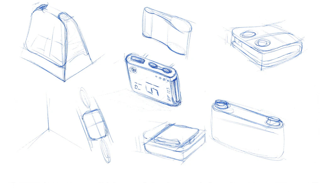
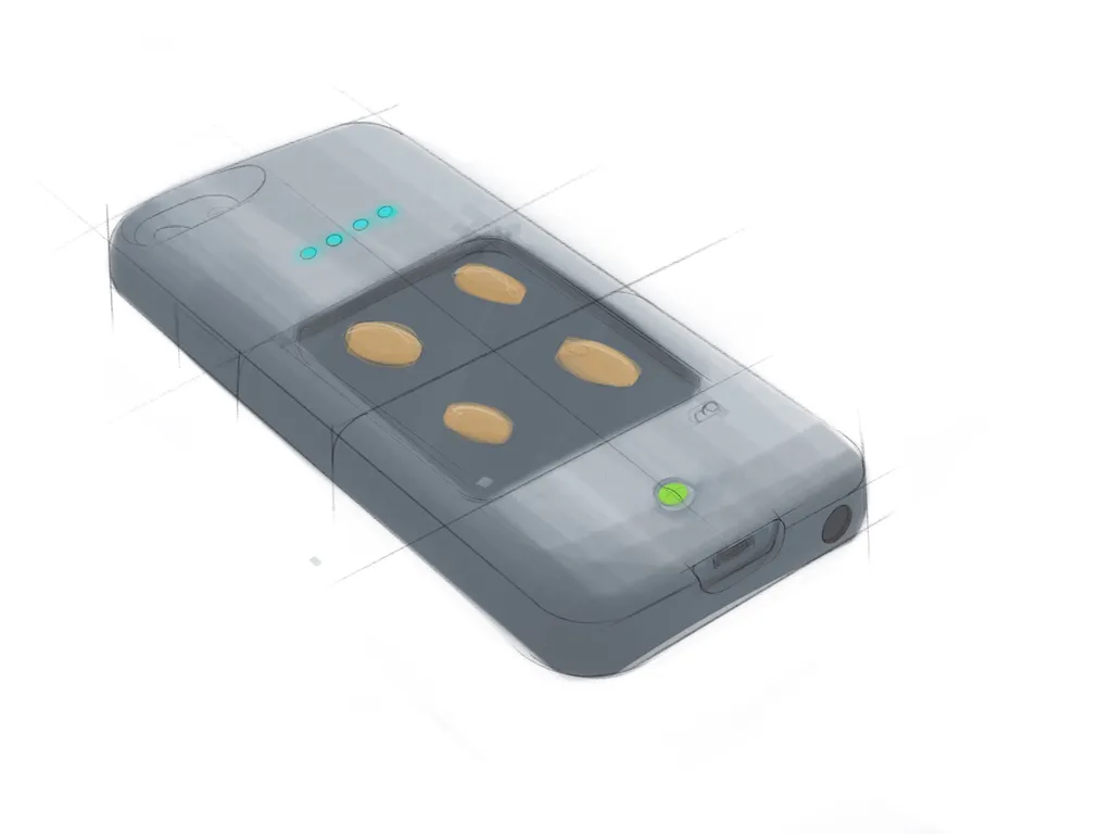
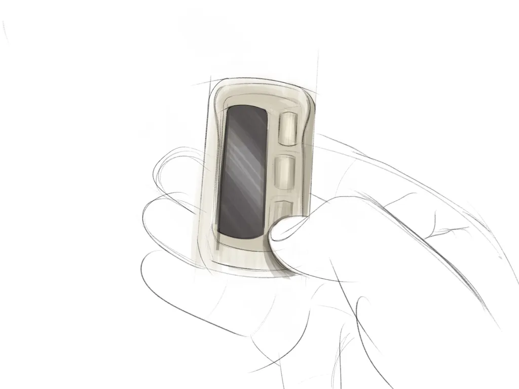
The patient handheld: Next Gen POP. Alongside the charger, the next generation of Nuvectra’s POP device went from sketch exploration to digital renderings. The concept notes call for a waterproof, wearable unit with Qi charging and smartphone pairing.



Outcome
Each goal had a specific design response. Here is where each one stood:
More robust: a flex-circuit connection option, an overmolded strain relief, and a high-reliability cable. These were part of the final paddle design handed to Engineering.
Easier to use: a single wearable unit with no assembly, a belt specification, a paddle shaped around the coil for alignment, and sound and tactile feedback. The paddle was handed off; the charger stayed a shared concept.
Lower cost: a goal of the brief from the start.
Prototyping was underway when the work hit an organizational limit. The paddle’s final industrial design went to Engineering as two options with multiple sub-options, but Engineering couldn’t resource the charger’s transfer to engineering designs, and Nuvectra wound down in 2019.
Review
A part is only as good as the routine around it. The most useful work on this project happened before any form: deciding what the paddle, the charger, and the cable each owed the patient. Handing off two well-defined options kept Engineering’s choice open, but a design only becomes a product when there is capacity to build it, and earning that capacity is part of the job.